The hidden controls that protect, regulate, and refine your hydraulic system
A Customer Guide
Most operators know the directional valve. The valves that quietly do the rest of the work are just as important.
Directional valves get the credit — they shift the cylinder, spin the motor, change the direction of flow. But every reliable hydraulic system relies on a supporting cast of pressure, flow, holding, and protective controls that decide how much, how fast, how smoothly, and what happens when something goes wrong. Below is a plain-English tour of the most common problems we see in the field, and the valve that solves each one.
The pump keeps running after a cylinder bottoms out, or a blocked port has nowhere for oil to go. Pressure climbs until something breaks — a hose, a fitting, a casting.
Solution
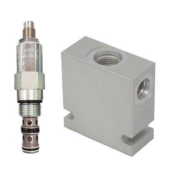
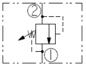
A relief valve is the system's pressure ceiling. Above the setpoint, it dumps excess flow back to tank, protecting every component downstream.
How it works: a spring holds a poppet closed; when system pressure exceeds the spring force, the poppet opens and oil bypasses to tank.
Anti-Shock / Cushion Valve
Pressure
Problem
A directional valve slams shut and the moving column of oil has nowhere to go. The result is a pressure spike that hammers seals, hoses, and pumps — often heard as a loud "bang."
Solution
A cushion or anti-shock valve absorbs the spike by momentarily venting a small amount of oil at a higher pressure than the relief setting, then resetting.
How it works: short-duration relief tuned to the spike, not the working pressure — protects without affecting normal operation.
Decompression Valve
Pressure
Problem
A large cylinder is loaded to high pressure. When the directional valve shifts, the trapped energy releases all at once — lurch, shudder, ringing in the lines.
Solution
A decompression valve bleeds trapped pressure down to a safe level before the main port opens, eliminating the jolt.
How it works: staged opening — a small bleed path opens first, then the full flow path opens once pressure has equalized.
2
Holding Loads & Preventing Runaway
Keeping the load where you put it — safely
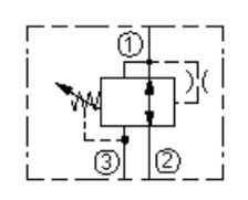
Counterbalance Valve
Holding
Problem
A boom or lift slowly drops under its own weight even when the directional valve is centered — or worse, it runs away when lowered.
Solution
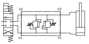
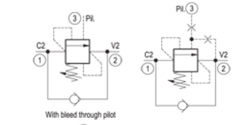
A counterbalance valve holds the load against gravity and only releases flow when pilot pressure from the opposite line tells it to. The load lowers smoothly, never faster than the pump commands.
How it works: spring-loaded closed; opens proportionally when pilot pressure from the “raise” line confirms a controlled descent is happening.
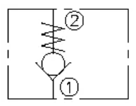
Pilot-Operated Check (PO Check)
Holding
Problem
You park a cylinder with a load on it and walk away. By morning it's drifted down because the spool valve has internal leakage.
Solution
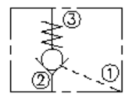
A pilot-operated check valve seals the cylinder shut hydraulically — zero drift — and only opens when pilot pressure on the other side gives permission.
How it works: a poppet seats against a hard surface (not a spool), giving a true leak-tight seal until pilot pressure unseats it.
Brake Valve (Motor)
Holding
Problem
A hydraulic motor driving a winch or wheel coasts past the stop, or accelerates uncontrollably when the load tries to drive the motor.
Solution
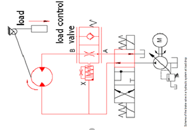
A brake valve (a counterbalance variant for motors) holds backpressure on the return line, preventing over-speed and giving controlled deceleration.
How it works: meters the motor’s return flow under load-induced overrun, slowing it predictably instead of allowing freewheeling.
3
Controlling Speed & Flow
Setting how fast things move
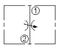
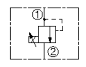
Throttle / Needle Valve
Flow
Problem
A cylinder moves too quickly for the operator or the application. You need a way to slow it down — cheaply.
Solution
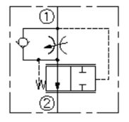
A throttle (needle) valve introduces an adjustable restriction. Smaller orifice, less flow, slower actuator.
How it works: a tapered needle screws into a seat to vary the open area. Simple, but flow varies with system pressure.
Pressure-Compensated Flow Control
Flow
Problem
An actuator slows down as the load increases, or speeds up when the load lightens. Operators can't get consistent cycle times.
Solution
A pressure-compensated flow control holds flow constant regardless of load pressure — same speed under any conditions.
How it works: an internal compensator senses pressure drop across the orifice and adjusts automatically to keep flow steady.
Deceleration Valve
Flow
Problem
A cylinder slams into its end-of-stroke at full speed, damaging the cylinder or shaking the equipment.
Solution
A deceleration valve gradually reduces flow as the cylinder approaches the end of travel, easing it into the stop.
How it works: a cam roller (driven by the moving part) progressively closes the flow path, ramping the speed down smoothly.
4
Splitting & Prioritizing Flow
When one pump feeds more than one job
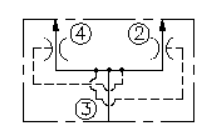
Flow Divider
Splitting
Problem
Two cylinders need to extend at the same rate, but one carries a lighter load and races ahead, jamming the structure between them.
Solution
A flow divider splits the pump's output proportionally (often 50/50) regardless of load, keeping both actuators synchronized.
How it works: two metering spools share a common shaft so flow to each outlet is forced to track the other.
Priority Valve
Splitting
Problem
Power steering and an implement circuit share the same pump. When the implement is working hard, the steering goes heavy.
Solution
A priority valve guarantees the steering (or any critical circuit) gets its full demand first; whatever's left goes to the secondary circuit.
How it works: a load-sensing spool reserves flow for the priority port and meters surplus flow to the secondary outlet.
Unloading Valve
Splitting
Problem
A two-stage pump (high-flow + high-pressure) is wasting power, heating the oil, and stalling the engine when the high-flow side stays loaded after pressure builds.
Solution
An unloading valve diverts the high-flow stage to tank once high pressure is reached, so only the small high-pressure stage carries the load.
How it works: senses system pressure; above a threshold, it opens a low-resistance path back to tank for one of the pump stages.
5
Different Pressures for Different Jobs
Reducing and sequencing inside one system
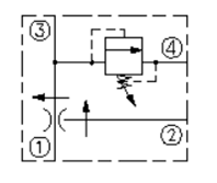
Pressure-Reducing Valve
Pressure
Problem
The main system runs at 3,000 psi, but a clamp circuit needs to hold delicate work at only 800 psi without crushing it.
Solution
A pressure-reducing valve gives the sub-circuit its own, lower pressure ceiling, independent of the main system.
How it works: closes proportionally as downstream pressure rises, locking the outlet at the setpoint even while inlet pressure climbs.
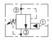
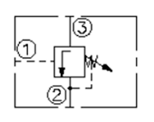
Sequence Valve
Pressure
Problem
A press needs to fully clamp the workpiece before the punch comes down — but the operator can't be trusted to always wait long enough.
Solution
A sequence valve holds the second circuit (the punch) closed until the first (the clamp) reaches full pressure. The sequence becomes automatic.
How it works: opens at a set inlet pressure, passing flow to the next circuit only after the first job is complete.
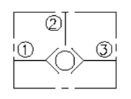
Shuttle Valve
Logic
Problem
A pilot circuit needs to respond to either of two pressure signals, whichever is higher — without one source backfeeding into the other.
Solution
A shuttle valve passes the higher of two input pressures to the output and isolates the lower one. Simple OR logic in hardware.
How it works: a ball or spool inside the body is pushed by the higher-pressure inlet, blocking the other.
6
Specialty & Multi-Coupling
When you need to connect several lines at once — or none of the above
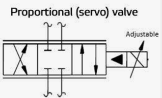
Proportional Valve
Electronic
Problem
You need variable speed, smooth acceleration, or programmable motion profiles — not just "all on" or "all off."
Solution
A proportional valve takes an electrical signal (current or voltage) and opens its spool in direct proportion. Drive it from a joystick, a PLC, or a closed-loop controller.
How it works: an electromagnet positions the spool against a centering spring; spool position determines flow.
Servo Valve
Electronic
Problem
A test stand, injection-molding machine, or precision actuator needs sub-millimeter positioning and millisecond response.
Solution
A servo valve closes the loop with the highest precision available — it's the surgical tool of the hydraulic world.
How it works: a torque-motor-driven flapper-nozzle stage steers a precision spool with continuous position feedback.
Cartridge / Logic Valve
Electronic
Problem
A custom machine needs a unique combination of functions and the budget won't allow a manifold full of discrete valves.
Solution
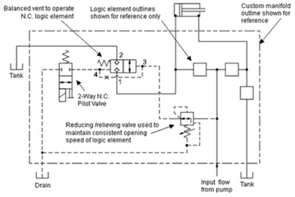
Cartridge valves screw into a machined manifold block and act as logic elements — you build the exact circuit you need, compactly, with shorter flow paths and fewer leak points.
How it works: each cartridge is a simple two-port logic element; combined in a manifold they form complete circuits.
Not sure which valve your system needs?
Bring us the symptom — the drift, the shudder, the slow cylinder, the heat — and we’ll tell you which control is missing, failing, or misadjusted. We service, rebuild, and source every valve type listed above.